


Description
[Description:]
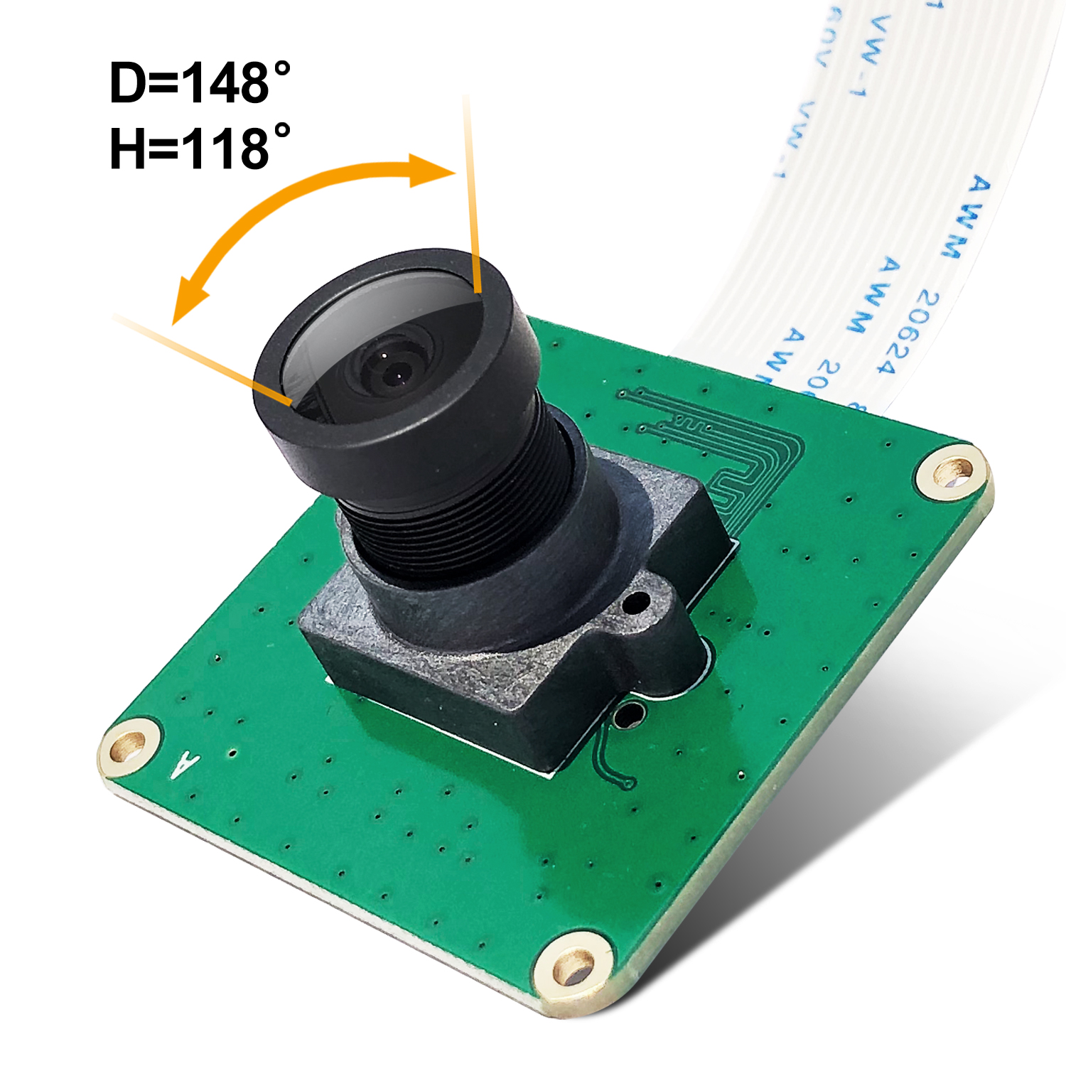
- CAM-MIPI290RAW-Color module with SONY IMX290LLR Sensor, and connects via a ribbon cable to the CSI connector on the Raspberry Pi. It is a fully V4L2 compatible device.
- CAM-MIPI290RAW-Color module can be connected to a number of RPI boards, like Raspberry Pi 4 3B+ 3B Zero A+ CM3+ CM3.
- CAM-MIPI290RAW-Color is an Industrial Camera Module for Raspberry Pi
- Sensor Type:
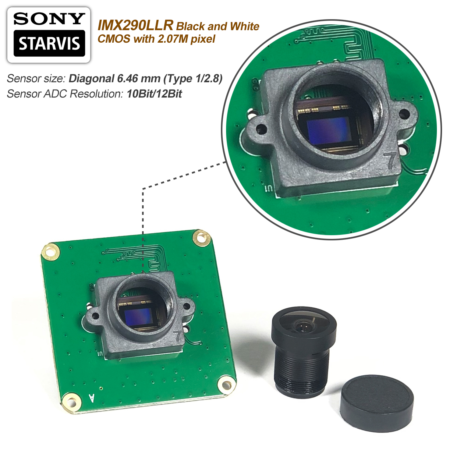
- SONY STARVIS IMX290LLR Color CMOS with 2.07M pixel.
- Pixel Size: 2.9(H)x2.9(V)um.
- Sensor size: diagonal 6.46 mm (Type 1/2.8).
- Sensor ADC Resolution: 10Bit/12Bit.
- CAM-MIPI290RAW-Color module connects via a ribbon cable to the CSI connector on the Raspberry Pi.
- CSI-2 output: 2 lanes/RAW10 or RAW12.
- CSI-2 default speed: 891Mbps/lane.
- It is a fully V4L2 compatible device.
- Fully Compatible with Raspberry PI Build In Driver
[Technical Parameters:]
- Sensor type: SONY STARVIS IMX290LLR Color CMOS with 2.07M pixel.
- Sensor size: diagonal 6.46 mm (Type 1/2.8).
- Sensor ADC Resolution: 10Bit/12Bit.
- CSI-2 output: 2 lanes/RAW10 or RAW 12.
- Pixel Count: 1920 x 1080.
- Pixel Size: 2.9(H)x2.9(V)um.
- CSI-2 default speed: 891Mbps/lane.
- Output modes: streaming mode.
- Shutter resolution: 1 horizontal unit.
- Gain: 0—72dB.
- Board Size:39mm x39mm.
- Connector: 15PIN 1.0mm FPC cable.
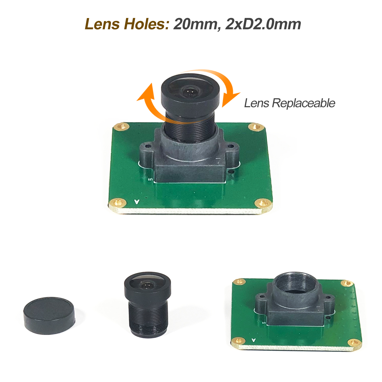
- Mounting Holes: 4XD2.2mm.
- Lens Holes: 20mm,2xD2.0mm
[Packing List:]
- CAM-MIPI290RAW-Color Camera Module
- 1x 15PIN Ribbon Cable
[Quick Start]
- Modify config.txt by command : sudo nano /boot/config.txt
- Add content and save config.txt, reboot:
- dtoverlay=imx290,clock-frequency=74250000
- Preview: libcamera-hello -t 0
To override the automatic camera detection, you will need to delete the entry camera_auto_detect=1 if present in the config.txt file. Your Raspberry Pi will need to be rebooted after editing this file.
|
NOTE
|
Setting camera_auto_detect=0 disables the boot-time detection completely. |
[Pins OUT Description]
Raspberry Pi Camera Pinout (15-Pin)
| Pin # | Name | Description |
|---|---|---|
| 1 | GND | Ground |
| 2 | CAM_D0_N | MIPI Data Lane 0 Negative |
| 3 | CAM_D0_P | MIPI Data Lane 0 Positive |
| 4 | GND | Ground |
| 5 | CAM_D1_N | MIPI Data Lane 1 Negative |
| 6 | CAM_D1_P | MIPI Data Lane 1 Positive |
| 7 | GND | Ground |
| 8 | CAM_CK_N | MIPI Clock Lane Negative |
| 9 | CAM_CK_P | MIPI Clock Lane Positive |
| 10 | GND | Ground |
| 11 | CAM_IO0 | Power Enable |
| 12 | CAM_IO1 | LED Indicator |
| 13 | CAM_SCL | I2C SCL |
| 14 | CAM_SDA | I2C SDA |
| 15 | CAM_3V3 | 3.3V Power Input |
Sensor Module Selection Guide
| Characteristic | IMX290 | IMX327 | IMX462 |
| Resolution | 1920×1080 (1080p) | 1920×1080 (1080p) | 1920×1080 (1080p) |
| Sensor Size | 1/2.8 inch (diagonal 6.46 mm) | 1/2.8 inch (diagonal 6.46 mm) | 1/2.8 inch (diagonal 6.46 mm) |
| Pixel Size | 2.9µm x 2.9µm | 2.9µm x 2.9µm | 2.9µm x 2.9µm |
| Technology | STARVIS Back-Illuminated CMOS | STARVIS Back-Illuminated CMOS | STARVIS Back-Illuminated CMOS |
| Pin Compatibility | Pin-compatible | Pin-compatible | Pin-compatible |
| G Sensitivity (digits) | 5486 | 10741 | 10741 |
| Frame Rate (fps) | Up to 120 | Up to 60 | Up to 120 |
| Near-Infrared (NIR) Performance | Good | Better | Best |
| Cost | Lowest | Medium | Highest |
| HDR Support | BOL-HDR | Multiple Exposure/Digital HDR | HCG Mode/HDR |
| Other Features | Mature driver support | Anti-reflective coating version (IMX327LQR1, sensitivity 2519 mV, SNR1s 0.17 lux) | High Conversion Gain (HCG) mode, superior noise control |
